
4.2
Owner's of the Amana Range AGG222VDW gave it a score of 4.2 out of 5. Here's how the scores stacked up:

10
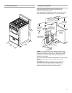
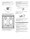
5. Close the broiler door.
6. Place burners, burner caps and grates on the cooktop.
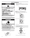
7. Plug into a grounded 3 prong outlet.
Check Operation
Electronic Ignition System
Cooktop and oven burners use electronic igniters in place of
standing pilots. When a cooktop control knob is turned to the
“LITE” position, the system creates a spark to light the burner.
This sparking continues until the control knob is turned to the
desired setting.
When the oven control is turned to the desired setting, a hot
surface igniter heats to a bright orange and ignites the gas.
No sparking occurs. The glow bar remains on while the burner
operates.
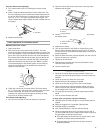
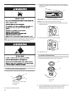
Check Operation of Cooktop Burners
1. If control panel and knobs were removed earlier, reinstall
knobs.
2. Push in and turn each surface
unit control knob to “LITE”
position. The flame should light
within 4 seconds.
3. Turn control knob to “HI”
position after burner lights.
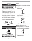
4. Check each cooktop burner for
proper flame. The small inner
cone should have a very distinct
blue flame
1
⁄4" (0.64 cm) to
1
⁄2" (1.3 cm)
long. The outer cone is not as distinct
as the inner cone.
5. Turn the control knob quickly to the “LO”
position after the burner lights. If the
flame goes out, turn the control knob to
the “OFF” position.
6. Check each cooktop burner for proper low flame. The low
flame should be a minimum, steady blue flame. The flame size
should be
1
⁄4" to
3
⁄8" (0.64 cm to 0.95 cm) high.
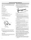
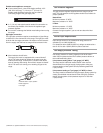
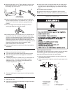
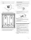
Typical flexible connection
1. Use a combination wrench to attach the flexible connector to
the adapters. Check that connector is not kinked.
Complete Connection
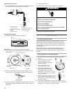
1. Locate gas pressure regulator in the broiler.
IMPORTANT: Do not remove the gas pressure regulator.
2. Check that the gas pressure regulator shutoff valve is in the
“ON” position.
3. Open the manual shutoff valve in the gas supply line. The
valve is “open” when the handle is parallel to the gas pipe.
4. Test all connections by brushing on an approved noncorrosive
leak-detection solution. Bubbles will show a leak. Correct any
leak found.
outer
cone
inner
cone
OFF
LO
LITE
MED
HI
A. Closed valve
B. Open valve
A
B
A
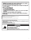
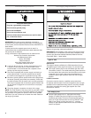
Electrical Shock Hazard
Plug into a grounded 3 prong outlet.
Do not remove ground prong.
Do not use an adapter.
Do not use an extension cord.
Failure to follow these instructions can result in death,
fire, or electrical shock.
WARNING
Shutoff valve
“ON” Position
Front
Front ViewFront View
Side View
Gas Pressure Regulator
A. Gas pressure regulator
C
E
G
H
A
D
F
B
A. Pressure regulator
connection fitting
B. Use pipe joint compound
C. Adapter
D. Flexible connector
E. Adapter
F. Use pipe joint compound
G. Manual shutoff valve
H.
1
⁄2" to
3
⁄4" gas pipe


Find Your Products By Category
- Lawn and Garden
- Computer Equipment
- TV and Video
- Laundry Appliance
- Kitchen Appliance
- Car Audio and Video
- Automotive
- Photography
- Fitness & Sports
- Personal Care
- Communications
- Home Audio
- Portable Media
- Musical Instruments & Equipment
- Baby
- Household Appliance
- Cell Phone
- Marine Equipment
- Outdoor Cooking
- Power Tools
- Video Game
Please Login
