

0
Owner's of the Lasko Cell Phone NOT FOUND gave it a score of 0 out of 5. Here's how the scores stacked up:
MODEL 2510
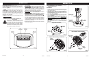
OPERATION (Figures 5 and 6)
This Fan may be operated by the Manual Controls located
on top of the unit (as shown in Figure 5) or by the Remote
Control (shown in Figure 6).
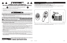
1. Place the Fan on a rm and level surface.
CAUTION: Plastic or rubber tabs, like the feet on this unit,
may stick to furniture surfaces and/or hardwood oors. The unit
may leave a residue that could darken, stain or leave permanent
blemishes on the nish of certain furniture surfaces, including
wood surfaces, and/or hardwood oors.
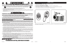
2. Plug the cord set into a 120 volt outlet.
Be sure that the plug ts tightly into outlet.
When plugs t loosely into receptacles, they
may slip partially or completely out of the re-
ceptacle with only the slight movement of the
attached cord. Receptacles in this condition
may overheat and pose a serious re hazard;
if covered by a curtain or drape, the re hazard
is even greater.
Rev. B 9/07
4
2510ES
Rev. B 9/07
9
2510ES
MODEL 2535
3. Turn the Fan ON by pressing the Power Button ( ).
4. SPEEDS: Press the Fan Speed Button ( ) to desired
speed setting. Each time the Fan Speed Button is pressed,
the speed will change from High (3), to Medium (2), to Low
(1). When the Fan is turned OFF and ON again, the unit will
resume the speed at which it was turned OFF.
5. OSCILLATION: Press the Oscillation Button ( ) to start
and stop the oscillation function.
6. TIMER: The timer function allows the unit to be set to operate
for a length of time from 1 hour to 7 hours, in increments
of 1 hour. Press the Timer Button ( ) to set the length of
time desired. Each time the timer button is pressed, the time
is increased by 1 hour. After reaching 7 hours, pressing
the timer button once more will reset the Fan to continuous
running. The lights on the front of the unit will light up
appropriately with the length of time that the Fan is set for.
7. To turn the Fan OFF, press the Power Button ( ) and unplug
the unit from the electrical outlet.
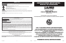
Figure 5
Oscillation
Button
Power
Button
Timer Button Speed Button
ENSAMBLADO
1. Cuidadosamente retire el ventilador de la bolsa plástica y de
la caja. Para facilidad de ensamblado, coloque el ventilador
en forma horizontal para que la parrilla frontal esté apuntando
hacia abajo.
2. Arme las Bases de Apoyo interconectando las Salientes en la
Base de Apoyo A dentro de los Oricios de Salientes en la Base
de Apoyo B. Introduzca el Cable Eléctrico a través del oricio
grande en el centro de la Montura de la Base de Apoyo. (Figura 1)
3. Asegure los (4) Tornillos #8 de X 9,9 mm en los cuatro oricios
de la parte inferior de la base. (Figura 2)
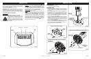
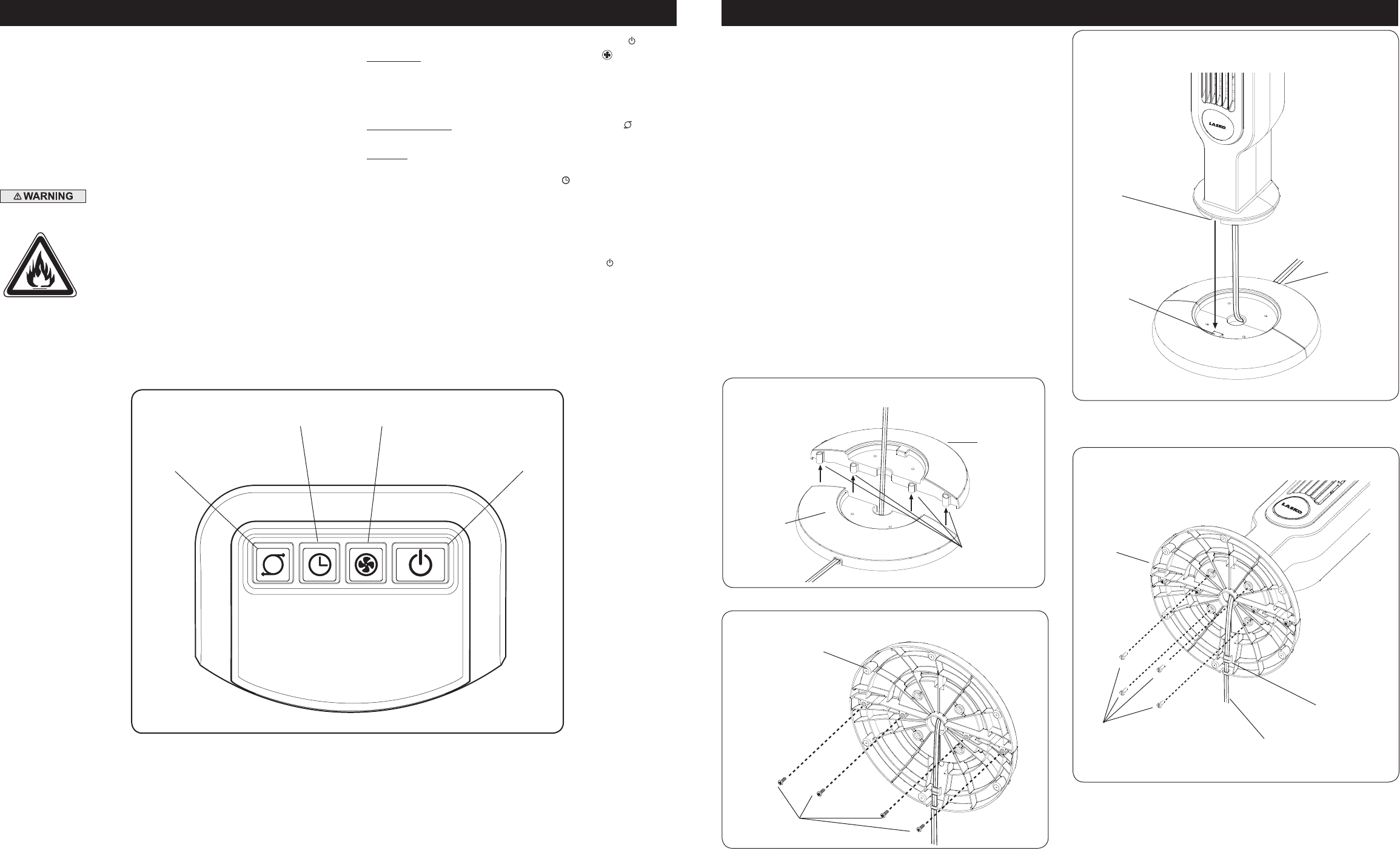
4. Alinee las Lengüetas de Alineación de la Montura de la Base
de Apoyo con las ranuras de alineación en la parte inferior del
ventilador, teniendo cuidado de que el canal del cable en la parte
inferior de la base de apoyo debe estar apuntando hacia la parte
posterior del ventilador. (Figura 3)
5. Asegure la Montura de la Base de Apoyo a la parte inferior del
ventilador con (4) Tornillos M5 de 12,7 mm de Largo. Suavemente
elimine cualquier sobrante del Cable Eléctrico y colóquelo en el
Oricio de Colocación del Cable. (Figura 4)
HERRAMIENTAS REQUERIDAS PARA EL
ENSAMBLADO (no incluidas)
- Destornillador de cabezal Phillips #2
Tornillos
M5 X 12,7 mm
Montura de la
Base de Apoyo
Cable Eléctrico
Oricio de
Colocación del
Cable
Figura 4
Montura de la Unidad de base a Parte Inferior
MODELO 2510
Figura 1
Base de
Apoyo B
Base de
Apoyo A
Salientes
Montura de la Base de Apoyo
Figura 2
Montura de la Base de Apoyo - Vista Inferior
Montura de la
Base de Apoyo
Tornillos
#8 X 9,9 mm
Canal del Cable
Lengüeta de
Alineación de la
Montura de la Base
de Apoyo
Ranura de
Alineación
Figura 3


Find Your Products By Category
- Lawn and Garden
- Computer Equipment
- TV and Video
- Laundry Appliance
- Kitchen Appliance
- Car Audio and Video
- Automotive
- Photography
- Fitness & Sports
- Personal Care
- Communications
- Home Audio
- Portable Media
- Musical Instruments & Equipment
- Baby
- Household Appliance
- Cell Phone
- Marine Equipment
- Outdoor Cooking
- Power Tools
- Video Game
Please Login
