
0
Owner's of the RCA TV Mount MAF15BKR gave it a score of 0 out of 5. Here's how the scores stacked up:
English
3
Attaching the Arms to the TV
IMPORTANT! Use extra
care during this part of the
installation. If possible, avoid
placing your display facedown
as it may damage the viewing
surface.
NOTE: This mount comes
with a selection of different
screw diameters and lengths
to accommodate a wide
variety of display models. Not
all of the hardware in the kit
will be used.
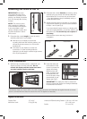
2. Determine the correct diameter of screw to use by
carefully trying one of each size (M4 and M6) from
the hardware kit. Do not force any of the screws
– if you feel resistance stop immediately and try a
smaller diameter screw.
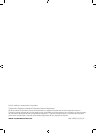
3. Attach the mount arms to the back of your display
using the M6 washers (I) and the screws identifi ed
in Steps 1 and 2 (see Fig.3)
If you are using the longer screws on a display with
a curved or recessed back, you will also need to use
the spacers (E). You should only use a spacer if
necessary.
Make sure the screws are snug, but do not
overtighten.
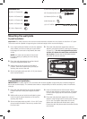
Fig.2
For displays with curved or
recessed backs.
For displays with
flat backs.
Fig.3
1. Determine the correct length of screw to use by
examining the back of your display:
A. If the back of your display is fl at and the
mounting holes are fl ush with the surface, you
will use the shorter screws (A or C) from the
hardware kit.
B. If the back of your display is curved, has
a protrusion, or if the mounting holes are
recessed, you will need to use the longer screws
(B or D) and spacers (E).
Specifi cations
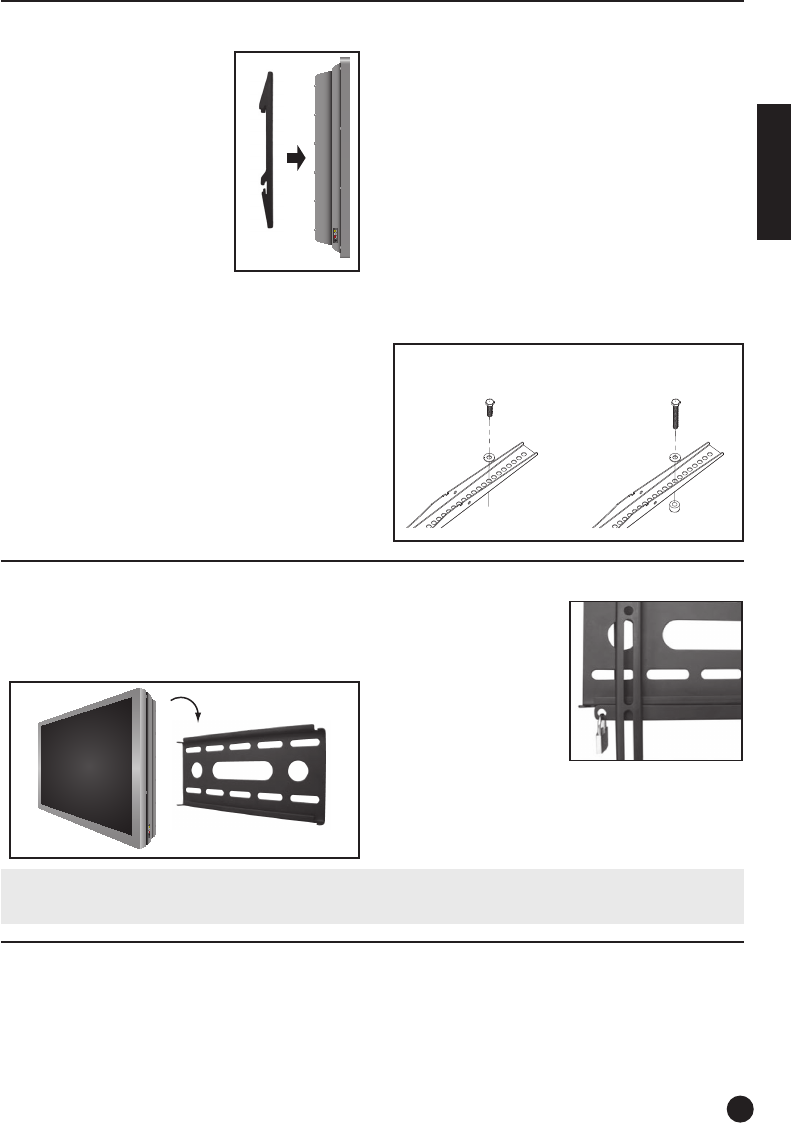
Final Installation
1. With the help of another person, carefully lift your
display and place it on the wall plate. Do not
release the display until the mount arms have
securely hooked onto the wall plate.
Fig.4
Fig.5
Periodically clean your mount with a dry cloth. Inspect all screws and hardware at regular intervals to ensure
that no connections have become loose over time. Re-tighten as necessary.
2. Insert the safety bar
at the bottom of the
mount to prevent the
display from being
lifted from the wall
plate. A padlock can
be inserted into the
end of the bar to help
prevent theft of your
display (see Fig.5).
IMPORTANT! The safety bar must be used at all
times to prevent the display from being accidentally
knocked from the mount.
Display Size: 15” to 32”
Maximum Load: 25 kg (55 lbs)
Universal VESA Mounting Pattern: 230 mm x 250 mm
(9” x 9.8“) max
Profi le: 2.2 cm (0.9”)


Find Your Products By Category
- Lawn and Garden
- Computer Equipment
- TV and Video
- Laundry Appliance
- Kitchen Appliance
- Car Audio and Video
- Automotive
- Photography
- Fitness & Sports
- Personal Care
- Communications
- Home Audio
- Portable Media
- Musical Instruments & Equipment
- Baby
- Household Appliance
- Cell Phone
- Marine Equipment
- Outdoor Cooking
- Power Tools
- Video Game
Please Login
