

4.0
Owner's of the Pioneer Car Stereo System Pioneer Car Stereo System gave it a score of 4.0 out of 5. Here's how the scores stacked up:
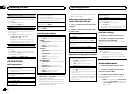
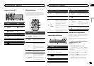

j When using a subwoofer of70 W (2W), be
sure to connect the subwoofer to the violet
and violet/black leads of this unit. Do not
connect anything to the green and green/
black leads.
k Not used.
l Subwoofer (4W)× 2
Notes
! With a 2 speaker system, do not connect any-
thing to the speaker leads that are not con-
nected to speakers.
! Change the initial menu of this unit. Refer to
SP-P/O MODE (rear output and preout set-
ting) on page 8.
The subwoofer output of this unit is monau-
ral.
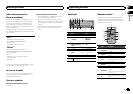
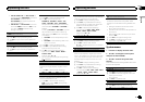
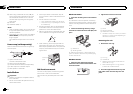
Power amp (sold separately)
Perform these connections when using the op-
tional amplifier.
1
3
2
4
55
1 System remote control
Connect to Blue/white cable.
2 Power amp (sold separately)
3 Connect with RCA cables(sold separately)
4 To Rearoutput or subwoofer output
5 Rear speakeror subwoofer
Installation
Important
! Check all connections and systems before
final installation.
! Do not use unauthorized parts as this may
cause malfunctions.
! Consult your dealer if installation requires
drilling of holes or other modifications to the
vehicle.
! Do not install this unit where:
— it mayinterfere with operationof the vehicle.
— it maycause injury to a passengeras a result
of a suddenstop.
! The semiconductor laser will be damaged if
it overheats. Install this unit away from hot
places such as near the heater outlet.
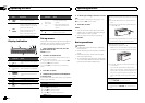
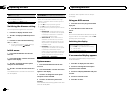
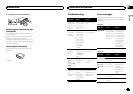
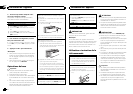
! Optimum performance is obtained when the
unit is installed at an angle of less than 60°.
60°
! When installing, to ensure proper heat dis-
persal when using this unit, make sure you
leave ample space behind the rear panel and
wrap any loose cables so they are not block-
ing the vents.
5cmcm
Leave ample
space
5 cm
5 cm
DIN front/rear mount
This unit can be properly installed using either
front-mount or rear-mount installation.
Use commercially available parts when instal-
ling.
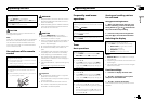
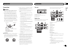
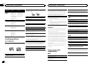
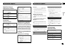
DIN Front-mount
1 Insert the mounting sleeve into the dash-
board.
For installation in shallow spaces,use the sup-
plied mounting sleeve. If there is enough space,
use the mounting sleeve that came with the ve-
hicle.
2 Secure the mounting sleeve by using a
screwdriver to bend the metal tabs (90°) into
place.
1
2
1 Dashboard
2 Mounting sleeve
# Make sure thatthe unit is installedsecurely in
place. An unstableinstallation may cause skipping
or other malfunctions.
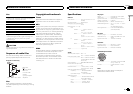
DIN Rear-mount
1 Determine the appropriate position
where the holes on the bracket and theside
of the unit match.
2 Tighten two screws on each side.
1
2
3
1 Screw
2 Mounting bracket
3 Dashboard or console
! Use either truss(5 mm × 8mm) or flush sur-
face (5 mm× 9 mm) screws,depending on
the bracket screwholes.
Removing the unit
1 Remove the trim ring.
1 Trimring
2 Notched tab
! Releasing thefront panel allows easierac-
cess to thetrim ring.
! When reattaching thetrim ring, point the
side with thenotched tab down.
2 Insert the supplied extraction keys into
both sides of the unit until they click into
place.
Installation
10
Section
Installation
En
03


Find Your Products By Category
- Lawn and Garden
- Computer Equipment
- TV and Video
- Laundry Appliance
- Kitchen Appliance
- Car Audio and Video
- Automotive
- Photography
- Fitness & Sports
- Personal Care
- Communications
- Home Audio
- Portable Media
- Musical Instruments & Equipment
- Baby
- Household Appliance
- Cell Phone
- Marine Equipment
- Outdoor Cooking
- Power Tools
- Video Game
Please Login
